September 2015
Introduction
Transportation agencies consider or specify the use of positive protection devices on a variety of project types. Some of the most common needs for protection include worker exposure to traffic, traffic exposure to drop-off conditions, and separation of opposing traffic flows. The Temporary Traffic Control Devices Rule (23 CFR 630 Subpart K) requires consideration of positive protection devices in work zone situations that place workers at increased risk from motorized traffic and where positive protection devices offer the highest potential for increased safety for workers and road users. Considerations for when to use positive protection include traffic characteristics, project duration, length of project, depth of drop-off condition, and worker exposure. Given a variety of considerations for which type of device to use, many agencies have developed guidelines for when to use positive protection and outlined characteristics to consider when designing or setting policy on use.
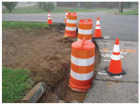
Figure 1. Drop-Off Condition with Limited Sight Distance
One of the most common types of positive protection is the F-shape portable (temporary) concrete barrier (PCB). However, PCB does not fit all situations. For intermediate- to long-term operations, a water filled barrier (where room for deflection is greater) or steel barrier may be practical due to added mobility. For shorter duration activities, shadow vehicles with attenuators may be more practical given limited setup time. The decision to use positive protection includes a number of factors, and practitioners match appropriate devices with the type of project that would most benefit from their use.
For example, work zone locations with two-way stop controlled intersections or hills with steeper driveway access may warrant additional considerations, such as sight distance over the top of the positive protection device. While F-shape PCB is commonly 32 inches tall, it may make sight distance an issue in some locations, and it may also be more protection than required if speeds are low. For these types of urban settings, water filled barrier is an option in that it can be placed and filled on site. However, it may limit sight distance and may deflect more than the lateral buffer space available behind the barrier. In many settings, devices must easily accommodate horizontal and vertical curvature. Additionally, designers want to ensure that positive protection devices themselves do not create an additional hazard.
Given that not all available devices both provide redirective capability and fit the sight distance needs of some low-speed urban situations, some States are using low-profile portable concrete barrier (LPB). Florida DOT and Texas DOT have used this type of device and have also developed standard details and specifications for its use. Texas DOT developed a transition segment (see appendix) especially for work zones that extends over long distances, where LPB is used in the low-speed urban section and PCB is transitioned in for the rural high-speed segments. Some States such as Washington and California have used LPB in permanent settings, with some experimenting and studying the use of LPB for temporary application.
This guide offers practical information on the use of LPB in moderate to low-speed work zones. Many urban and suburban work zones may not be good candidates for traditional PCB because of its size, installation requirements, room for placement, and impacts to motorists’ line of sight.
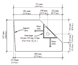
Figure 2. University of Florida Design (Cross Section)
Purpose of the Low-Profile Barrier
The purpose of a low-profile barrier (LPB) is to shield the work space and redirect errant vehicles, while improving drivers’ visual range. LPBs offer protection for moderate- to low-speed work zones in urban and suburban locations with the added benefit of reducing line-of-sight issues while providing for safer work spaces without additional impact to traffic safety. LPBs are made of precast reinforced concrete and are manufactured in sections that connect to form a continuous barrier.
LPB has an approximate height of 18″ to 20″ in 12 foot sections, while most current PCBs have a height of 32″. Urban and suburban work zones benefit from the improved range of vision through better driver performance at intersections, side street approaches, and temporary roadway configurations. Urban and suburban work zones present a significant opportunity to improve safety for workers and road users in a challenging roadside environment where space is limited and access to driveways and side streets is needed. These lower speed locations can be considered for LPBs based on cost effectiveness, constructability, and logistical requirements.
LPB was approved for use by FHWA beginning in 1998 as an NCHRP 350 test-level 2 device. More recently, a NCHRP 350 test-level 3 LPB has been developed that uses a stabilizing rail attached to the barrier. Many early tests were performed on a pre-cast LPB, ultimately leading to some expanded permanent use applications.
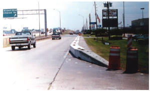
Figure 3. LPB with End Terminal
Safety and cost benefits provide the potential for expanded use of LPB as a design alternative to traditional PCB on applicable projects. Texas DOT, Florida DOT, and Caltrans are a few agencies that have tested and currently use the low-profile design and are good information resources for those interested in pursuing LPB for work zone applications.
Benefits of Low-Profile Barrier Use
Some specific benefits of LPB include:
User Benefits — Pedestrians, workers, and drivers all benefit from LPB protection since it improves visibility and offers positive protection. Urban/suburban work zones are challenging due to the need to maintain vehicle access, turning movements, and channelization, all while also maintaining line of sight. These challenges can lead to serious work zone intrusion crashes. LPB can provide protection for a variety of road users, as well as workers who are in close proximity to traffic, whereas the typical F-shape PCB with end treatment might hinder line of sight.
Work Types that May Benefit from Use — Road widening, utility work, and roadside development may result in hazardous work zone conditions such as excavations and drop-offs. These conditions often require hazard mitigation to ensure safety of workers and road users. The close proximity of traffic and high speeds in these work zones can result in crashes, including run-off-the-road crashes.
Florida DOT specifies use of LPB for secondary roadway widening projects, especially at interchange ramp intersections, to ensure adequate sight distance.
Constructability Benefits— Urban and suburban work zones are typically very dynamic in their work and traffic control operations. LPB accommodates this type of work zone well and introduces positive protection as a cost-effective and constructible alternative, as well as these other benefits:
Reduced need for channelization devices in urban low speed settings — LPB establishes a defined work space that uses fewer temporary channelization devices that need continual maintenance, like traffic cones, while also providing protection. Florida DOT does require use of supplemental devices on top of the barrier, and also requires use of a vertical panel at the beginning of the barrier section. Efficiency in installation, removal, and remobilization — Efficient installation and resetting or removal may be simpler in many situations over the larger traditional PCB that may not be a good candidate for urban and suburban projects. LPBs use a short radius for curvature along transitional sections.
Cost efficiencies in re-use — LPB sections are reinforced concrete that can more easily be repaired and reused. PCB may be re-used up to 8 times and then need replacement. Once specified and purchased, contractors will have inventory or can either rent barrier sections if needed or purchase from other contractors and re-use the sections.
Maintenance Benefits — LPB designs for most work zone applications do not need to be anchored in place. LPB sections are easily connected by steel horizontal pins and also allow for simple replacement of damaged components. Any damaged LPB components are easily repaired due to the simple modular design. Site preparation is minimal and the design is likely acceptable (10:1 or flatter cross slope) for most project locations where the barrier will be located along the existing roadway prism. Designs are available that allow for smooth transitions from low-speed urban to high-speed urban or rural areas for longer length work zones, allowing users to transition from a low-profile cross section to the F-shape cross section.
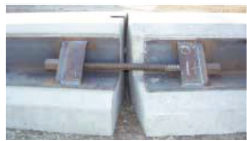
Figure 4. Section Connecting Pin (Florida Design)
Constructability Benefits — LPB can be placed more quickly than PCB using a forklift, thereby potentially reducing exposure in the installation and removal phase.
Safety of Barrier Ends — The design may not include any end treatment. However, agencies provide requirements for flare rate, proximity to intersections/driveways, and radii for curvature. One State requires use of warning panels at the end of the barrier section, with additional visibility from devices placed on top of the barrier. Be sure to follow the manufacturer’s requirements and any requirements from the crash test results.
Operational Features of the Low-Profile Barrier
LPBs have several important operational features, that should be considered when LPBs are assessed as an alternative to traditional PCBs.
- LPB has a one-inch inverted face (away from traffic at the bottom of the section) designed to keep the vehicle low on impact. PCB translates horizontal momentum into vertical rise, using an opposite face design to that of the LPB.
- LPB has a higher cost than PCB; therefore, benefits such as ease of placement, ease of flaring on horizontal and vertical curves, and improved safety performance through enhanced sight distance can be included in the analysis to determine cost effectiveness. Given that LPB may have a longer life than PCB, consider life cycle cost analysis to determine feasibility.
- Compact size of LPB allows easy placement in tight configurations that may require angled sections with sharper flare rates. It is easy to set and reset at the work site using a forklift, as opposed to the larger equipment required for placing PCB and the need for a lane closure with PCB.
- Effectively prevents unwanted access without the need for anchoring to the pavement and with relatively low deflection. Florida DOT reports that LPB deflection was minimal under the crash tests (up to 9 inches) as compared to non-anchored PCB deflection of up to two feet.
| Barrier Type | Average Market Price1Per Linear Foot |
|---|---|
| PCB with JJ Hook | $28/LF |
| K-Rail PCB (anchored type) | $38/LF |
| Low-Profile Barrier | $105/LF |
The following section outlines some of the operational characteristics of projects that may be good candidates for use of LPB.
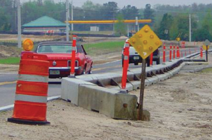
Figure 5. LPB with Standard Delineators and Warning Panel
Typical Speed — LPB offers a similar level of protection compared with PCB for moderate- to low-speed work zones in urban and suburban locations, 45 mph and below.
Typical Volume Levels — In terms of need for positive protection, urban and suburban work zones present a significant opportunity to protect workers and road users while providing for traffic access to businesses, parking lots, and side streets. Volumes may be moderate to high, and non-recurring congestion may be present. The goal should be to maintain existing traffic mobility levels. LPB generally accommodates that goal with its minimal footprint, good visibility, and flexible location requirements.
Worker Exposure — Workers are protected by use of temporary LPB, while adequate line of sight for adjacent and turning traffic is maintained. Trucks entering and exiting the traffic stream may also be more visible over the barrier. Drop Off Conditions – Work zone conditions at urban and suburban locations may include excavations and drop-offs that require hazard mitigation to meet work zone standards. The close proximity of traffic presents a higher potential for a pedestrian-vehicle crash or a work zone intrusion.
Practice Examples in Use
Several State DOTs have a design for and use LPBs. The following table compares design details from Texas and Florida, two primary users of LPB, along with a comparison with traditional PCB.
| Device | Barrier Height & Width | Typical Section Details | Speed Threshold | Supplemental Devices Used | End Treatments | Deflection |
|---|---|---|---|---|---|---|
| Florida Low Profile Barrier | 18″ on side facing traffic; 28″ wide base | 12′ length reinforced concrete pre-cast sections (5,000 lbs. typ.) | ≤ 45 mph | Tubular markers at 50′ centers on tangents and 25 centers on radii | Trailing end flares with object markers are required at driveways | 9″ |
| Texas Low Profile Barrier | 20″ in height; 28″ wide base | 20′ length reinforced concrete pre-cast sections (7,000 lbs typ.) | < 45 mph | N/A, there is a low-profile to F-shape transition segment detail | Portable concrete end treatment design (type II) | Up to 9″ with joint failure — a retrofit design limits to 4″ |
| Traditional Portable Concrete Barrier | 32″ in height’ 24″ wide base | Varies, commonly 10′ or 20′ sections; 460 lbs/LF | All | Type C Warning Lights or delineators every 96′ to 100′ | Require a crash terminal if within clear zone | Up to 2′ (unanchored) up to 45 mph |
Suggested LPB Implementation Process
State DOTs may have a process in place for introducing new products. Agency champions may consider developing a resource package for stakeholders that includes a statement on the need for the product, costs, specifications, design information, and overall expectations for use and decision-making. Partnering with industry representatives (such as fabricators and possibly contractor associations) will also help with the process of identifying pros and cons, costs, benefits, production rates, and overall use guidelines.
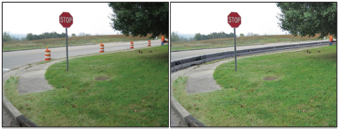
Figure 6. LPB Rendering Example – Same Location Without and With the Protection of LPB
The following list outlines a suggested process for implementation.
- Program funding for research and deployment.
- Allow time to procure the design license,2 if needed.
- Solicit interest from the device manufacturing industry in the form of a request for information.
- Develop specification for use on projects.
- Develop decision tree for application of LPB (determine which project characteristics are most important) and provide examples based on practices from other States.
- Develop design standards for LPB.
- Incorporate product information into an existing Qualified Products List (QPL).
- Pilot use on a project — issue request for proposals, award contract to pre-cast manufacturer.
- Include specification in project plans.
- Evaluate process, costs, benefits, and lessons learned and integrate into decision-making on use of positive protection for work zones.
Summary
Traditionally, PCB has been used in countless work zones and has proven its value over and over by providing positive protection against worker exposure to high-speed traffic and road user exposure to potential hazards associated with work zone intrusions. LPB accomplishes a similar positive protection function, but is intended for moderate- to low-speed applications within urban and suburban work zone conditions.
LPBs for work zones offer positive protection that otherwise may not be practical or cost effective, or may limit line of sight for entering vehicles. Positive protection in work zones is extremely desirable given transportation agencies’ limited ability to close roads or otherwise safely separate traffic from the work area.
As part of an engineering study, National, State and local agency work zone safety requirements specific to worker protection and work area positive protection and separation should be examined to determine if LPBs offer an opportunity to satisfy those requirements.
The information in this document is intended to provide useful information for understanding LPBs and their applications in moderate- to low-speed work zones. Appropriately planned and designed, LPB is an effective tool in the positive protection toolbox.
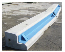
Figure 7. Florida LPB Design
Resources, Guidance, and Design Details
FHWA Public Roads Publication on Basics of Concrete Barriers
https://highways.dot.gov/public-roads/marchapril-2000/basics-concrete-barriers
Florida DOT Design Standard for Portable Temporary Low-Profile Barrier for Roadside Safety: https://fdotwww.blob.core.windows.net/sitefinity/docs/default-source/content2/roadway/ds/12/idx/00412.pdf?sfvrsn=371e75b2_0
Florida DOT/University of Florida Research Report:
https://fdotwww.blob.core.windows.net/sitefinity/docs/default-source/research/reports/fdot-bc976.pdf?sfvrsn=271305de_2
Texas DOT Standard Drawings for Low Profile Concrete Barrier Types 1 and 2 and End Treatment Design:
ftp://ftp.dot.state.tx.us/pub/txdot-info/cmd/cserve/standard/roadway/lpcb13.pdf
City of La Porte, Texas Specification for Use of Low Profile Concrete Barrier:
www.ci.la-porte.tx.us/DocumentCenter/Home/View/1844
CalTrans Research on Low-Profile Barrier Options and Uses:
http://www.dot.ca.gov/newtech/researchreports/preliminary_investigations/docs/low-profile_barriers_preliminary_investigation.pdf
AASHTO Technology Implementation Group Market Ready Technologies Report:
http://tig.transportation.org/Documents/AdditionallySelectedTechnologies-AST/LowProfileBarrier-TIGAST(10-2007).pdf
Appendix — Standard Drawing Examples
Figure 8. Florida DOT Standard Detail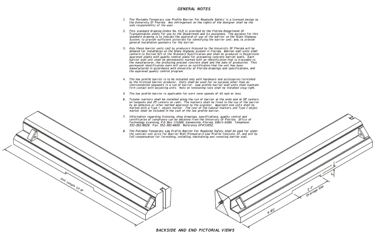
Figure 9. Florida DOT Standard Detail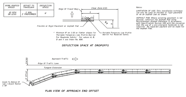
Figure 10. Florida DOT Standard Detail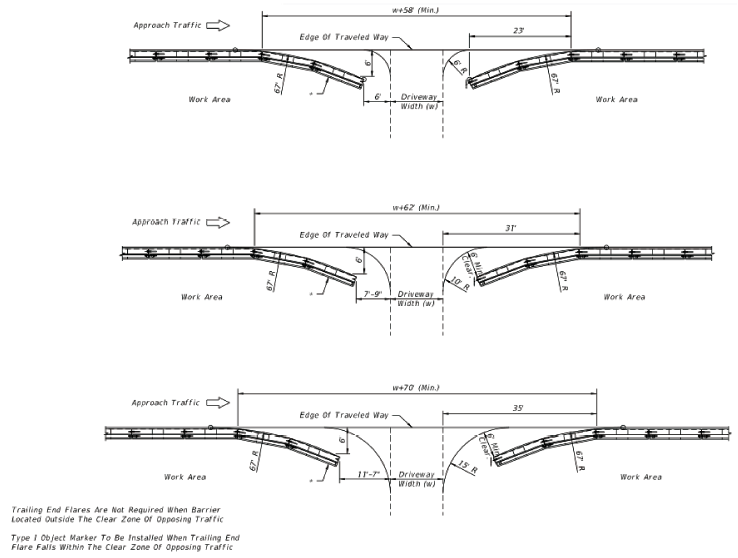
Figure 11. Florida DOT Standard Detail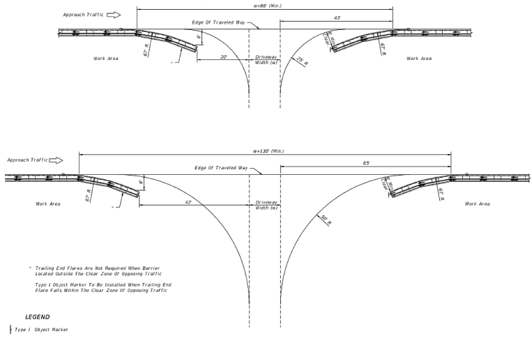
Figure 12. Texas DOT Standard Detail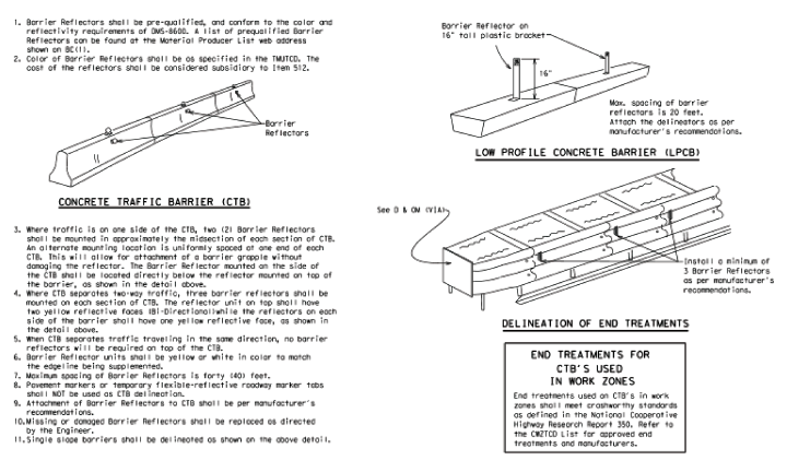
1 Estimated by industry representatives in Florida, not including freight and installation.
2 The low-profile concrete barrier examples used in Florida are based on a design licensed by the University of Florida.
Posted: 9/25/2015